Case study
House Water Dome
The prototype of a connected sprinkler controller meant to protect a house from wildfires: we designed its circuit board, its embedded software and the apps that configure it and control it remotely.
The project at a glance
- Client
- House Water Dome
- Sector
- Wildfire protection for homes
- Platforms
- Web, macOS, Windows, Linux
- Our role
- Electronics design, embedded software and apps for the prototype
The need
What the client needed
House Water Dome is working on a self-protection system for homes against wildfires: installed on the house, the system sprays it with water, and retardant if needed, so that the areas to defend are too wet to burn.
Before going further, the project needed a prototype to prove it was feasible: a controller able to start and stop a motor pump, open and close solenoid valves and check that water is actually flowing, triggered remotely from an app.
That controller had to bring together on a single board the 24-volt AC supply of the solenoid valves, the inputs of the pressure and flow sensors, and the network link. The electronics, its software and the apps were therefore designed together.
Our role
What we did
Maxime, an engineer at Web App Art, built the prototype end to end: the electronics, designed in-house with KiCad, the board's software, the configuration app, the owner's app and the server that connects them.
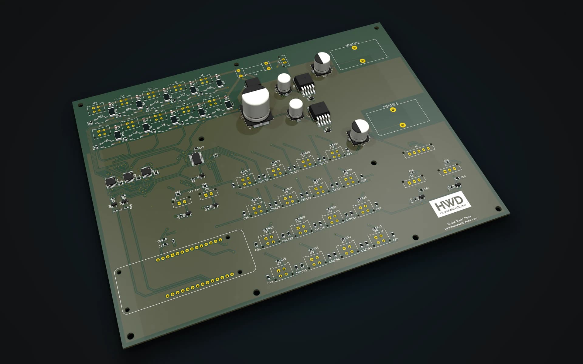
- The main board in KiCad: schematics, PCB layout and manufacturing files
- The motor pump control module, on a separate relay board
- The embedded software in C++ on Arduino: state machine, sensors and communications
- The desktop app that configures the board over USB
- The owner's web app, designed for the phone
- The Node.js server and its MQTT broker, linking the controller to the app
- A monorepo sharing the interface and types between the apps
- The prototype's technical documentation: architecture, equipment and wiring
Features
Key features
An expansion board for Arduino
Designed in KiCad, the board hosts an Arduino from the MKR family, derives its own 5 and 12-volt supplies from 24 volts AC, and multiplies its outputs and inputs with shift registers and an analogue multiplexer.
Ten solenoid valves driven
Ten 24-volt AC outputs, switched by photorelays that isolate the logic from the power circuit: the water inlet, the priming tank, the retardant tank and the spray lines.
Sensors on every line
Sixteen analogue inputs for pressure and level sensors and buttons, and two inputs for pulse flow meters. All wiring goes through Molex Micro-Fit connectors.
The motor pump, controlled remotely
A separate relay module, on its own board, powers the motor pump and works its starter on command from the main board.
A program that checks for water
A state machine runs priming, motor start, flow and pressure checks, then spraying line by line and the pauses between cycles. With no pressure it moves to the next line; with no water it restarts the motor up to three times before stopping.
Linked over the cellular network
The board connects over NB-IoT or LTE-M, or LoRaWAN depending on the Arduino model, and exchanges its state and errors over MQTT. Connecting does not block the program, and an on-site button can start or stop spraying.
A configuration kept on the board
A desktop app detects the board plugged in over USB and reads and writes its configuration, which the board keeps in flash memory: number of cycles, pauses, which tanks are fitted, and the order and duration of the spray lines.
The session, as a timing chart
Before sending the configuration, the app draws how a session will run: the lines opening one after another, the cycles and the pauses.
An app for the owner
From their phone, the owner connects to the house, turns protection on after a confirmation, runs a test mode or stops the current session. In the prototype, the figures shown are still demonstration values.
Screens
The project on screen
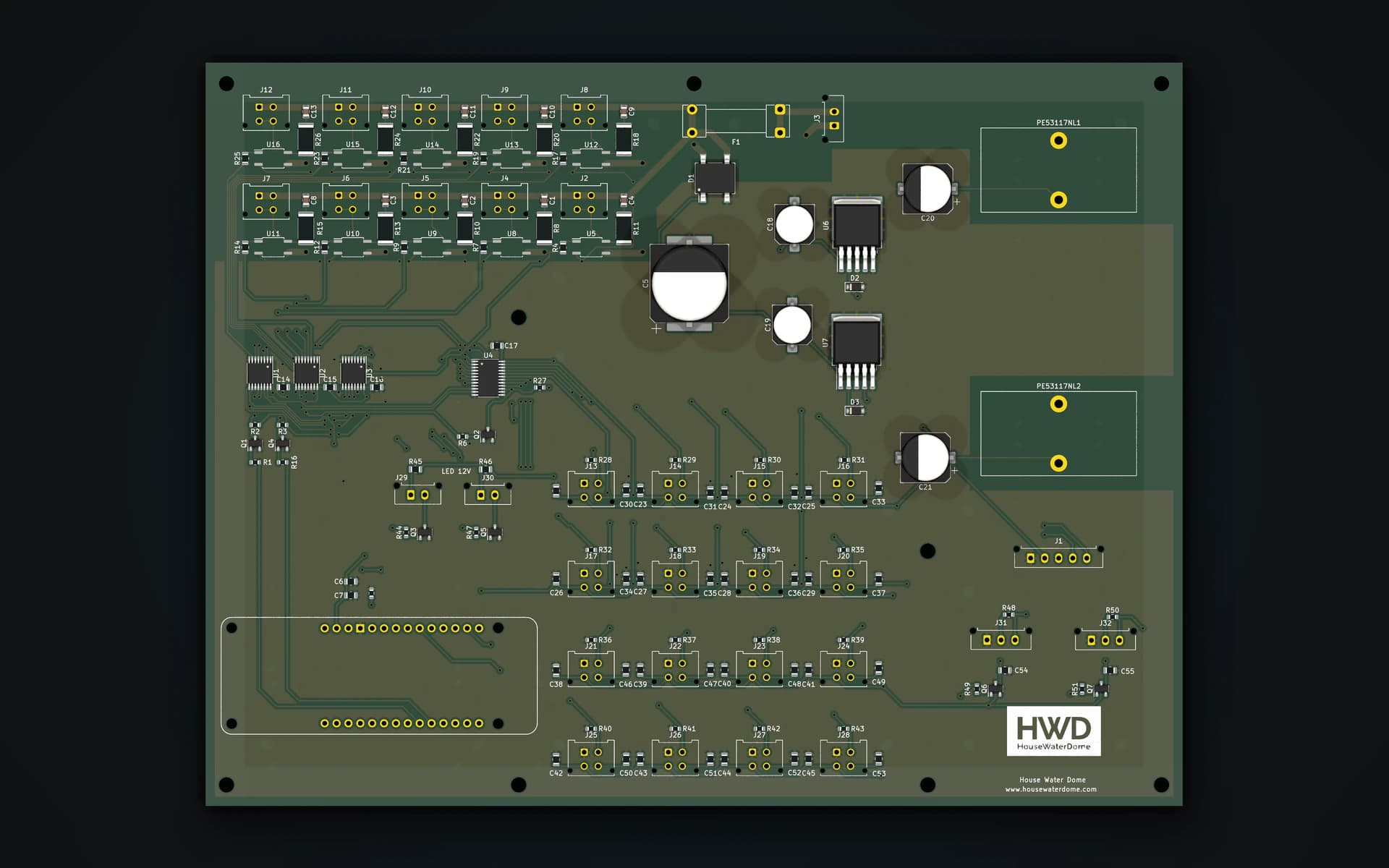
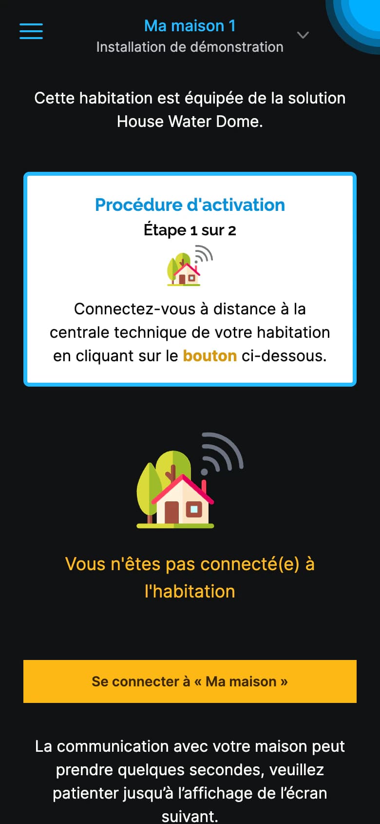
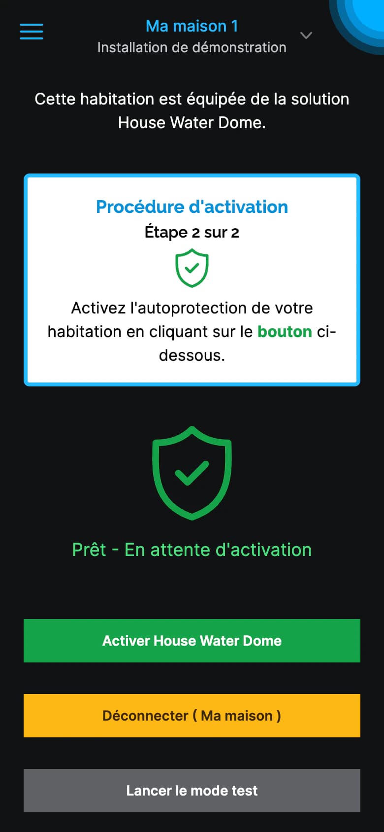
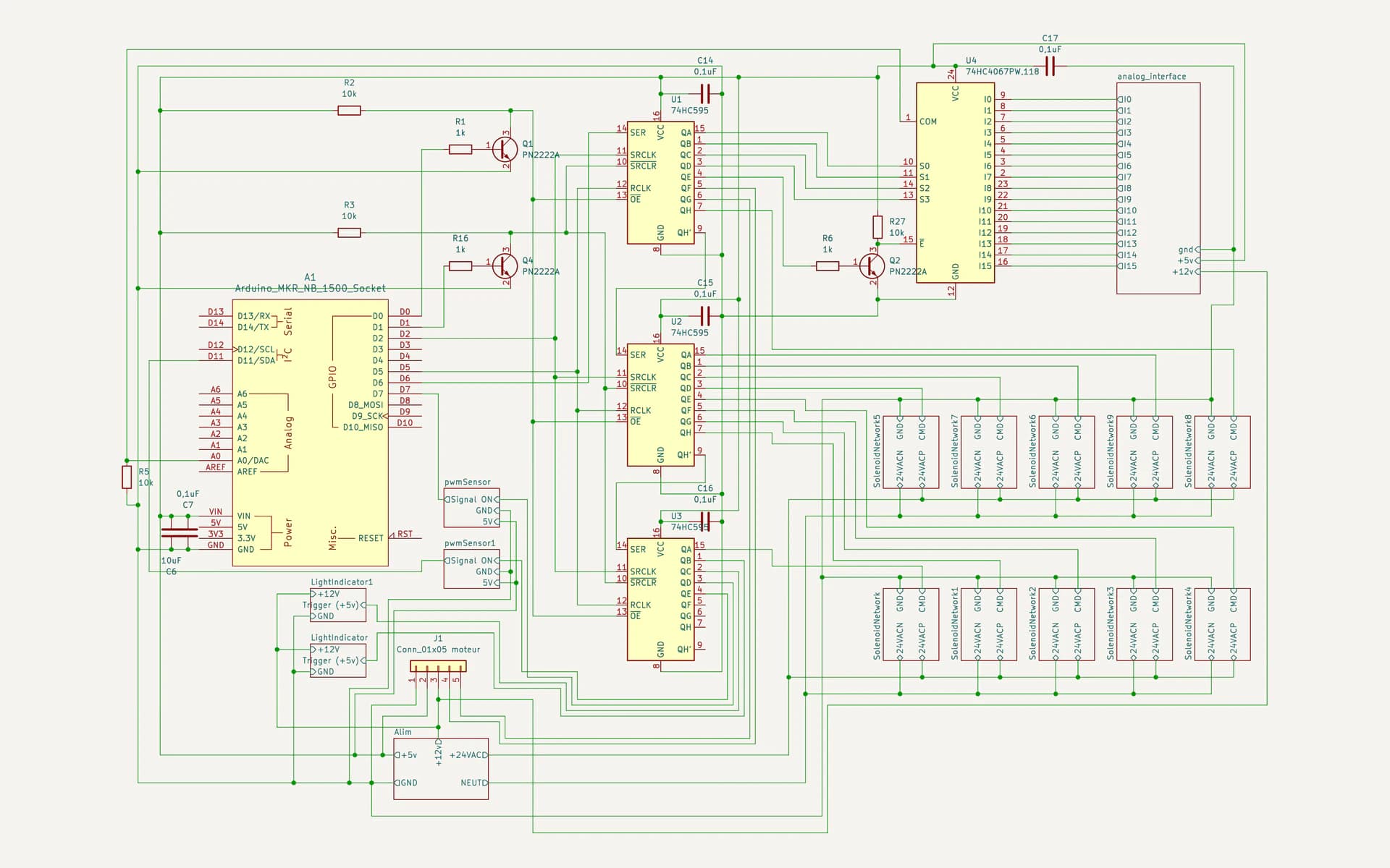
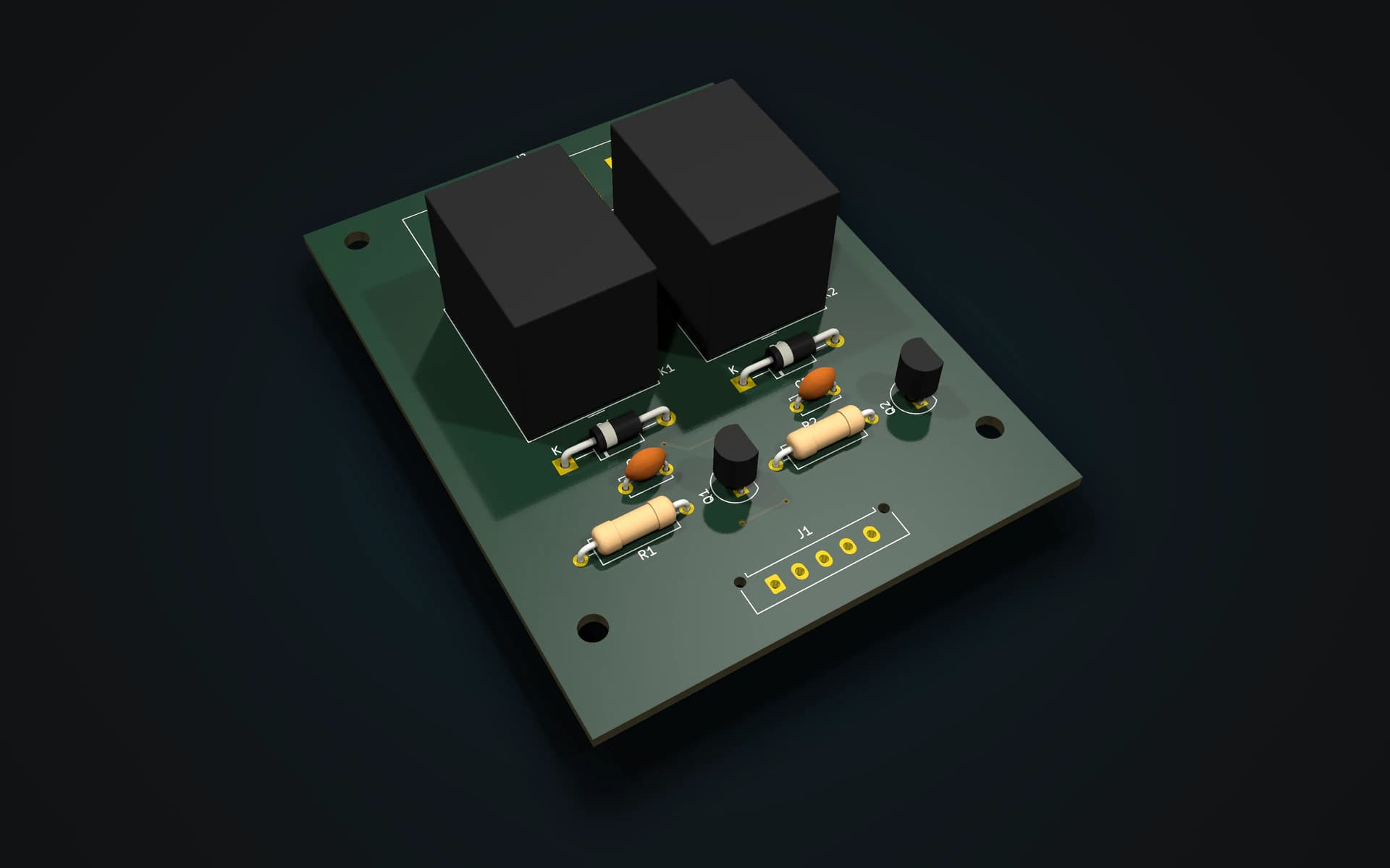
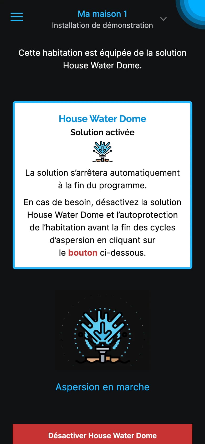
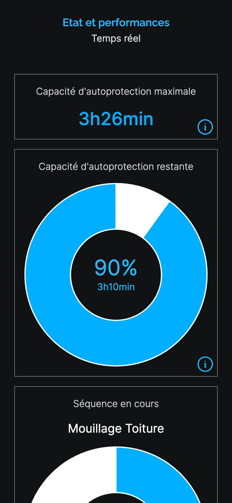
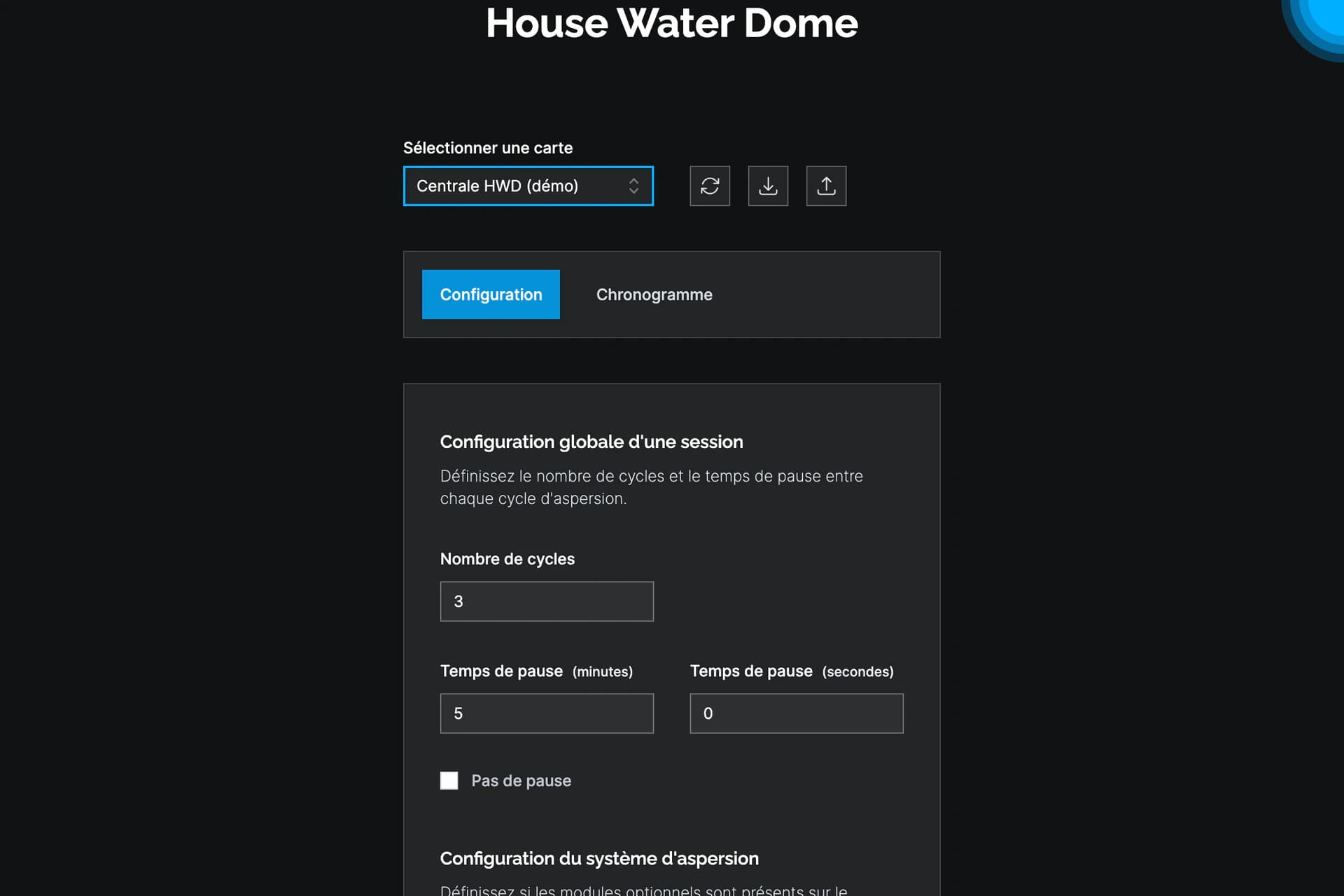
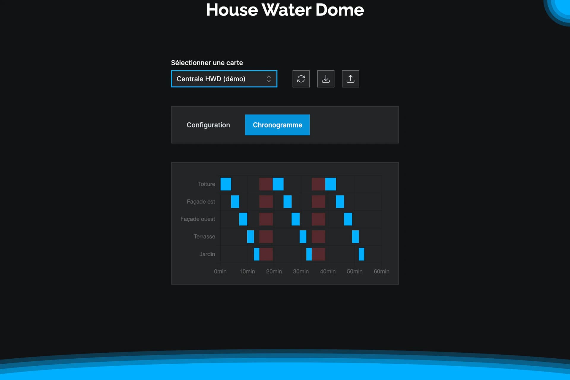
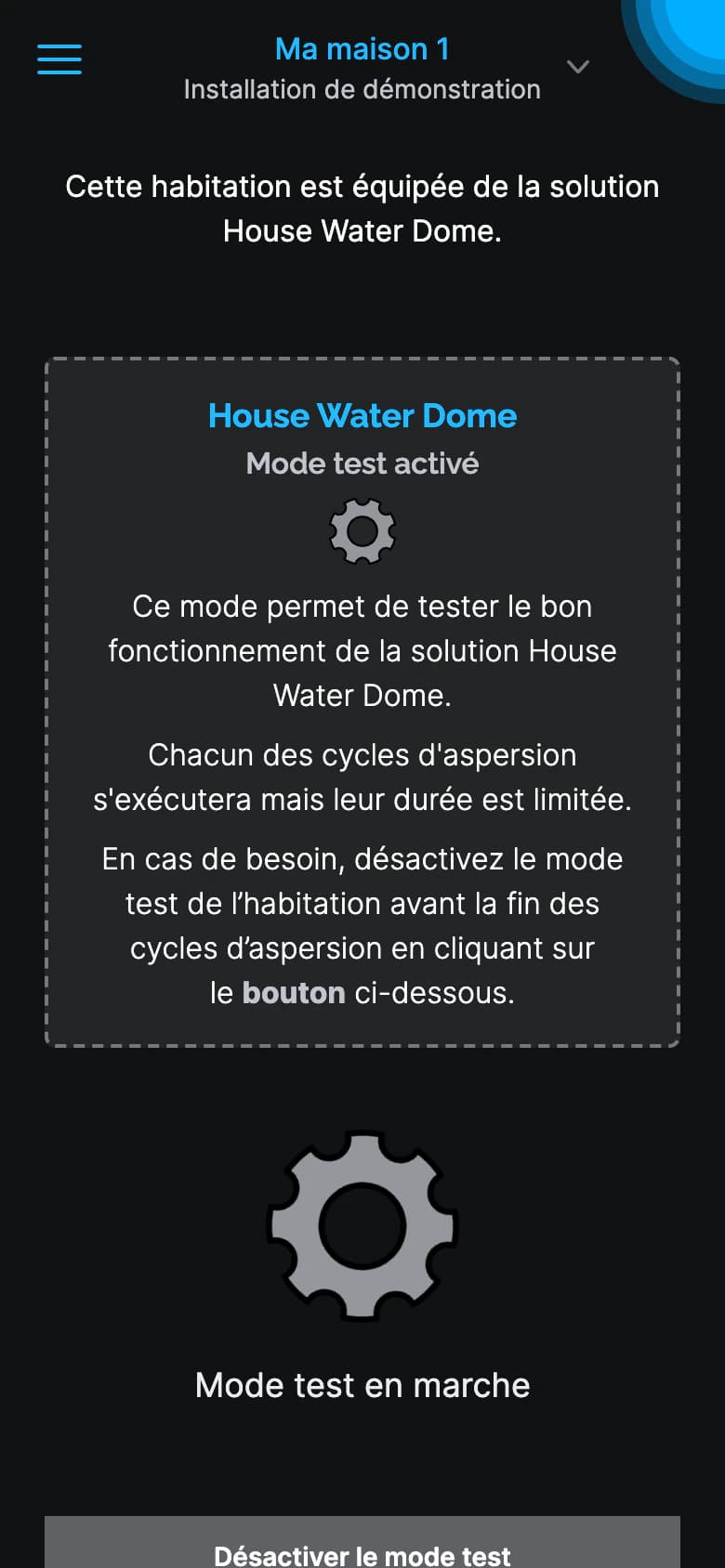
The 3D renders and the schematic come from the project's KiCad files; a few components with no 3D model in the KiCad library only appear as their footprint. The app screens come from the prototype's code run locally: the houses, lines and values shown are fictitious.
Technologies
Technologies used
- KiCad
- Arduino
- C++
- MQTT
- NB-IoT / LTE-M
- LoRaWAN
- Next.js
- React
- TypeScript
- Tailwind CSS
- Turborepo
- Tauri
- Rust
- Node.js
- Firebase
- Chart.js
Have an app project?
Tell us what you need: we will get back to you to set up a first meeting, with no commitment.